![]()

|
|
|
|
|
|
|
Ram Air Project
Began: November 2, 2001
Objective: To determine the most efficient ram air intake system for any given vehicle based on VE (Volumetric Efficiency) and feasibility.
The Project: I began by researching ram airs made as aftermarket add ons and looking at a lot of people that had made home brew ram air intakes. I noticed that there was very little if any actual research done to determine what was the best angle, hose size, scoop type for a ram air intake. The more I looked into ram airs, it seemed a lot of people just assumed if you stuck a hose out in the wind you'll get 15 horsepower.
So the project began, the next step was to do some modeling and experiment. The first experiment I ran was to figure out how restrictive different scoops were (based on geometry and area). I acquired several different scoops, and tested them with a High Power Turbo Honeywell fan and a strain gauge I made. All scoops were tested five times with three different air flow rates (to minimize error and variations from test to test). The results were all scoop geometries (even cones that had a larger inlet than outlet) all let through the same amount of airflow based on their area. From this experiment I concluded the only factor that matters for an intake scoop is the area of the scoop. This is contrary to what a lot of ram air manufacturers and some ram air gurus claim, a lot of them say that cone / wedge like scoops will 'draw in' more air than just a circle of the same area outlet, my research and experiment says no.
From this I moved on to testing mediums to transfer this large
amount of air from the scoop into the air box. Like most things in a car,
bigger seemed to be better, so I tried to find the largest types of hoses I
could find. The largest diameter hoses I could find was 3" aluminum
ducting, but it was ribbed, and 2.5" radiator hose. I wanted to use only
straight walled hose for the experiment, because I thought that ribbed tubing
didn't flow well. But then I thought about it, even if ribbed hose was 5%
more restrictive a 3" hose is 20% larger in diameter than a 2.5" hose.
Using the same strain gauge setup that was used for testing scoops I found that
3" ribbed wall aluminum ducting pushed 31.64% more airflow than 2.5" smooth wall
radiator hose. I made a smooth walled 3" tube out of a sheet of
flexible plastic and
sealed the seam. Using the strain gauge I measured the airflow through the
smooth walled 3" tube and would that ribbed hose only restricts airflow by 0.21%.
Why
do aftermarket and performance orientated gurus make such a big deal about
ribbed tubing then? A dirty air filter or a slightly angled tube does
multitudes more to restrict airflow. So that is the next experiment hose
angle.
I wanted to determine how much of a restriction hose length, angle of airflow relative to scoop/hose and angle of hose has on airflow. Again I used the same strain gauge setup I have used in the last for the previous experiments. I did the experiment on the 3" aluminum ducting, with lengths of 4.25", 7.5", 32" and 72.5". After I tested all the different length hoses at three different air flow rates I determined that air flow is not effected by the length of a tube (all lengths measured the same amount of airflow at 4.25", 7.5", 32" and 72.5" with the same air flow into the hose). I then checked of the angle of airflow relative to the scoop/hose effected airflow through the hose. I was mainly concerned about this because from how I understood air flow, a scoop facing straight forward, 180 degree with respect to the road surface (parallel to the road), would have the greatest air flow. But I noticed a lot of Trans Am ram airs had their scoop located at nearly 100 degrees with respect to the road. So I tested angle of angle of airflow with the strain gauge system and here is the results:
|
 |
> is the angle relative to the surface of the road, d is the displacement of the strain gauge
The experiments shows that the greatest air flow is going to be achieved by having the scoop be parallel to the road (180 degrees) or as close as possible. Even 20 degrees (the difference between 160 and 180 degrees) means a 49.25% loss of air flow. So why the heck are Trans Am ram airs all facing down at 110 degrees? The only thing I can think of is it must be the only place you could put a ram air in a Trans Am without having to drill a hole in something (like the hood). But just think about it, if a Trans Am nets 15 horsepower from a 110 degree intake, which is 545% more restrictive than a 180 degree scoop (what we are about to build)....
The next test is to determine how angles of hose restrict air flow. This is pretty straight forward, if you take a 10' hose and bend it 90 degrees right in the middle of the hose you would restrict the air flow a certain amount, what I needed to figure out was how much of a restriction was created. I used the same strain gauge setup for measuring air flow and the same 3" aluminum ducting. These are the results I recorded:
| > | d | % loss |
| 0 | 6.70 | 0 |
| 10 | 6.43 | 4.03 |
| 25 | 6.09 | 9.10 |
| 45 | 5.71 | 14.78 |
| 60 | 5.37 | 19.85 |
| 75 | 5.05 | 24.63 |
| 90 | 4.83 | 27.91 |
> is the angle that the hose is bent, d is the displacement of the strain gauge, and % loss is the percentage of air flow that is lost by bending the hose x degrees. It is nice to see that even a 90 degree bend doesn't kill off all the air flow, though we will try to avoid them. The other thing we can extrapolate from the data table is that the loss of air flow is linear, the amount of air flow lost at 90 degrees is double the loss at 45 degrees. The other thing I checked is that restrictions in series only add together. In other words if I create a 50 degree bend in the hose, and after that a 25 degree bend, the loss of air flow is equal to one bend of 75 degrees.
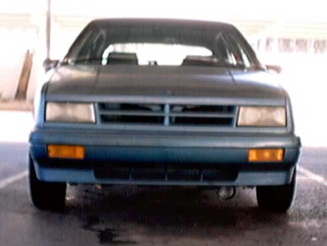
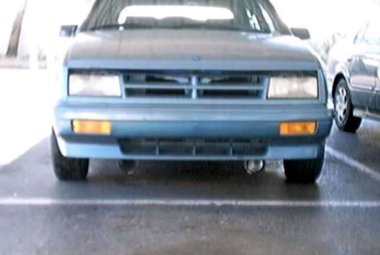
The last experiment I did was to determine were on the body of a car there would be most air flow. We can now eliminate any locations were the scoop and hose can not sit at 180 degrees relative to the surface of the road. So that only leaves the hood, inside of the fascia, under the car and the sides of the car. I had to tape hoses to all the points on my 1993 Dodge Shadow 2.2 L NA to measure the airflow inside of the car (mainly because the amount of air was too great to have the sensor outside of the car). I made sure that each tube was judged with equal weights (I determined the restrictions of each tube because of different angles, and used a weighted scale for each point). From my readings the greatest air flow was directly under the fascia and right over the top of the hood. This is interesting because there has to be some line on the front of a car were air flows up over the hood, and air below that line flows under the car, it seems to be almost exactly midpoint between the hood line and the bottom of the fascia. Which means there would be no lose in locating the scoop under the hood vs. on top of the hood.
Now it is time to begin modeling, complex models are not really needed after all the research and experimentation I did. From all the experiments I have already pretty much shaped what type of ram air should be built. A large area scoop, with the largest area hose that can be attached to the scoop and as few bends in the hose as possible located either on top of the front line of the hood or directly under the car. That limits us pretty much to only two places on the Dodge Shadow, and one will require making a 3" hole in the hood for no gain in airflow into the scoop. My first model, for a scoop on top of the front line of the hood shows that there would have to be 45 degrees total of bend to get from the scoop to the intake, that would create a 14.78% loss of air flow from the scoop to the inlet. The only other location is directly under the hood, which would require 135 degrees total of bend to get from the scoop to the intake, that would create a 42.69% loss of air flow from the scoop to the inlet. To me, a 28% difference in air flow wasn't worth a 3" hole in my hood for an experiment (especially since we've already seen that our scoop angle has 545% more air flow than the Trans Am ram air).
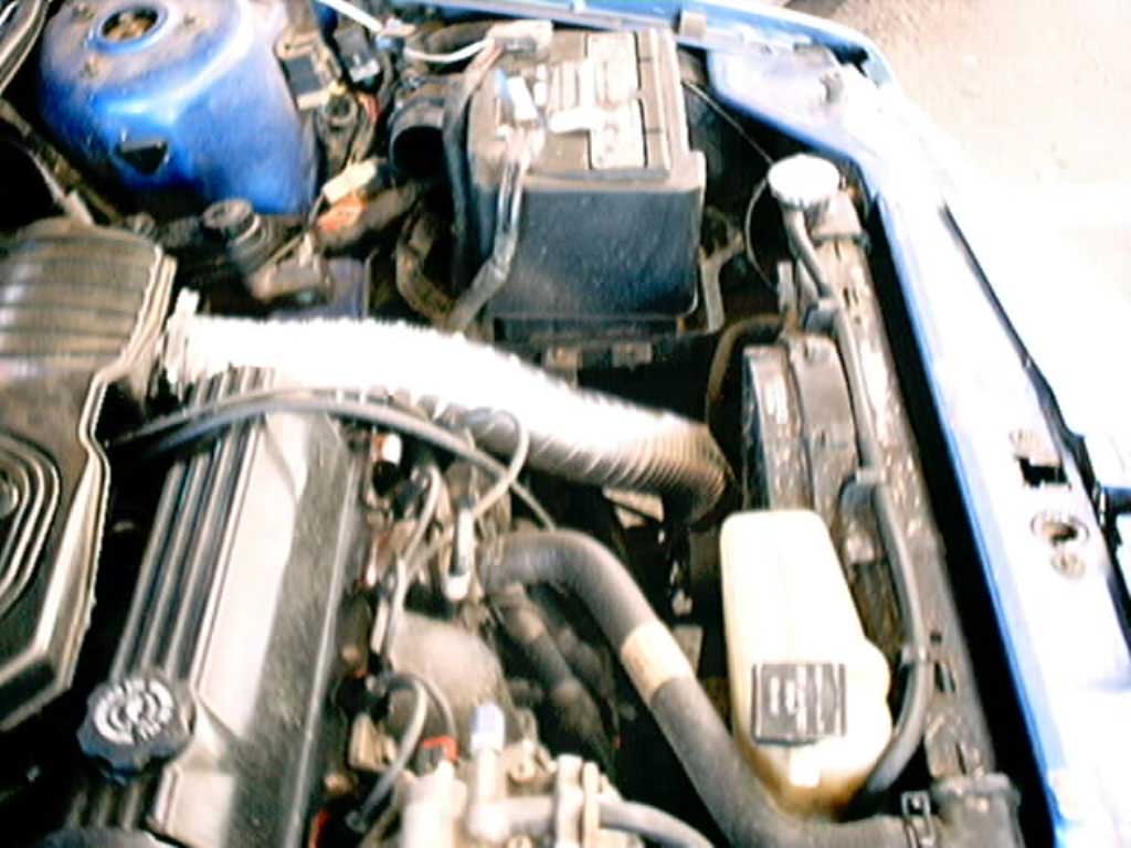
First Design: After all of the experiments and two different models we are ready to build the first design. It is pretty simple to install, the scoop is a 3" pipe coupler found at Home Depot for $1.79, a worm clamp ($1.69) attaches it to the beam that the radiator sits on (there are two holes which perfectly line up with the width of the coupler to feed the clamp through). The hose is 3" aluminum ducting (remember from the experiment, 10' was $5.99) and another worm clamp is needed to attach it to the stock air box. I sealed the 3" aluminum ducting to the coupler, else it will fly out of the coupler. The 3" aluminum ducting is rated for 5000 fpm (56.82 MPH) which worried me at first, but I have since had the car up to 125 MPH and have held over 90 MPH for extended periods of time with no problems what so ever.
Results: Wow, that's about all I have to say. The 2.2 sounds much throatier and deeper toned, I figured the ram air would help at higher speeds and probably do nothing starting from the line......wrong. The car will now take off much, much faster. Accelerating at highway speeds was never a friend of my 3 speed 2.2, but now it is a breath. There is a lot more high speed and high end power that was not there before, but there is also a good increase in torque at the low end. The K&N stock filter works fine even here in Mesa, AZ were there is a lot of dust (it was just fine through a dust storm during testing). I attempted to get water up into the air box but was unable to, it appears that it can not get up over the climb the ducting makes over the transmission, so another plus to the design. The only thing I am disappointed in is the stock air box. It is designed, very, very poorly for adding on a ram air. It is not sealed, it has a lot of holes in it, it is extremely restrictive, and for that reason I will have to modify it (read the air box modification).
Second Design: The first design worked great, but I modified the air box (read the air box modification - it is now only 4.78% restrictive, it was 78.3% restrictive stock) and I want to make up that 28% difference in air flow I lost placing the scoop under the hood with 135 degrees of bend. Answer? Two scoops (a dual ram air intake) instead of one. I placed the second scoop on the opposite side of the same beam the first one is located at (there are two holes for the worm clamp on this side also), because of the lower radiator hose this side will have 160 degrees of bend, so it is 46.72% restrictive, but the 53.28% of air that is allowed to get through easily makes up for the 28% difference in air flow. Another 3" hole is cut into the plastic portion of the air box for this hose.
Results: More power across the board, a little deeper tone, and if you stand up to six feet in front of the car and someone slams on the gas in neutral you can feel the pull from the dual intakes. The high speed acceleration was increased much more than the low speed acceleration (which one would except since more air would be flowing into the dual intakes at 50 MPH then at 0 MPH). Another benefit, a huge increase in fuel economy, a 5.1 MPG increase.
Third Design: I saw a good increase from a single scoop inlet to dual inlets, why not add a third one? The "I'm never satisfied" portion of this project has taken me over. One thing I did not except from the ram air would be lower engine temperature. I knew a cooler, denser charge of air would be drawn into the engine, but I didn't think it would cool down the engine, but it does. The 2.2 L NA test car runs about 9 degrees cooler at 75 MPH at the temperature sensor. The temperature under the hood decreased by 15 degrees at 75 MPH and the temperature above the butterfly is the same as ambient temperature (whatever the temperature is outside, that is what your air temperature is inside of your throttle body) at 55 MPH (before the ram air it was 76 degrees over ambient temperature). This alone (a 76 degree change in intake temperature) is worth 3.8% more horsepower (or 3.5 hp on a bone stock 2.2L NA engine). So after seeing this great decrease in temperatures all over the place, it was time to add a third scoop for more cooling. The throttle body and air box is already overloaded with air, so where can a third ram go to? The ECM on a stock intake is located right next to the battery on the end of the intake tube. With the stock intake, cool air is constantly drawn across the ECM while the vehicle is running, after this mod no air is drawn across the ECM. Bingo, a perfect place for the third ram to feed air to. I placed a 1.75" straight walled hose inside of the fascia (you can attack it the plastic with a metal band around the hose and anchor that into the fascia) and ran that to the ECM. The ECM should not overheat even without the ram air to it, but better safe than sorry, and the real reason for the third ram was to cool under the hood even more (the back of the ECM housing curves and points like a scoop directly across the engine).
Results: Believe it or not the engine is 2 degrees cooler and the temperature under the hood is another 10 degrees cooler.
Four Design: This really goes under the Matt never stops tweaking things category. I didn't like the look of three rams, and Tri Ram Air sounds pretty lame, so a fourth will be added. The fourth one will half ram the Crankcase filter mod I have already done. When the air box was modified, the crankcase to air box hose was removed. The forth ram is 1.75" straight walled hose at the opposite end of the fascia from the third ram. The hose connects to a larger 4" chamber made out of PVC pipe inside of that chamber is a K&N filter connected to the crankcase vent connector that use to go to the air box. I recommend this chamber because it highly restricts the flow of air (by 75 to 80% depending on speed), it is only a vent and a lot of air is not needed (though nice cold air is). I would recommend putting the crankcase vent on a K&N filter, it will keep your oil cooler (10 degrees pretty much at any speed), it will slow down the warming up of your oil (so if you do a lot of short trips, then it may not be for you), and should prolong the life of your seals and head gasket (as well as your engine since your oil is cooler). Since you cooling down your oil, you should pick up a little horsepower gain from a greater thermal efficiency, but it'll be pretty small (but I calculated it's range anyway on my mod calculation spreadsheet) .
Final Project Conclusions: I finished all the projects by mid December 2001 and have the Quad Ram Air in permanently on my 1993 Dodge Shadow 2.2L NA. The K&N filter, Quad Ram Air, heavily modified air box, and crankcase vent mod / filter / ram all work together very nicely for a huge gain in performance and fuel economy. I saw a 57.9% increase in fuel economy (but I wasn't getting the stock EPA fuel economy rating, it nets a 20% improvement over the EPA rating). Horsepower based on 1/4 mile time says I gained 36.6% (34 HP), which I account mainly to the very poor breathing of the stock 2.2. My mods to my car may be a little severe for some people, and like every mod on a car you are trading off one thing for another.
![]()
Copyright © 2004 Karlsnet.com. All Rights Reserved.
[an error occurred while processing this directive]